
This is the first in a two part post where I calculate the size and mass respectively of the Death Star in Episode IV (DS1). At the end of Part II I will discuss thoughts about the energy source of DS1.
Part I: Size of DS1
Conventional wisdom from multiple sources places the size of DS1 to about 100-160 km in diameter. Based on an analysis of the station’s plans acquired by the Rebels, I estimate that the diameter of DS1 is 60 kilometers, not 100 km to 160 km. To bolster the case, this scale is compared to other scales for self-consistency, such as the width of the trench leading to the exhaust port in the Battle of Yavin. Part II of the post will focus on the mass of DS1 using related methods.
To estimate the size of DS1, I will begin with the given length scale of the exhaust port w = 2 m. This information was provided in the briefing prior to the Battle of Yavin where the battle strategy and DS1 schematics are presented. This scale, when applied to Figure 1, is consistent with the accepted length of an x-wing L = 12.5 m. I assume that the x-wing has an equal wingspan (there does not seem to be consistent values available). I am also assuming that the “small, one-man fighter” referred to in the briefing is an x-wing, not a y-wing. The x-wing is a smaller, newer model than the y-wing and it is natural to take that as the template. The self-consistent length scales of w and L will establish the length calibration for the rest of the analysis.
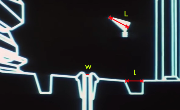
Figure 1: A close up view of the exhaust port chamber during final phase of the bombing run. The port width is given as w = 2 m. The length of the x-wing is L = 12.5 m. The forward hole, of length l, is then determined to be about 10 m.
From this, I extract the length of the smaller forward hole in Figure 1 to be approximately l = 10 m.
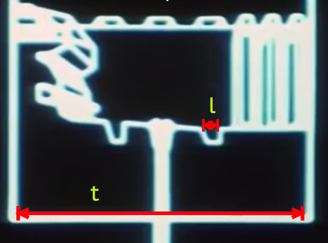
Figure 2: As the plans zoom out, a larger view of the exhaust port chamber of width t = 186 m. The first hole is shown with width l = 10 m. The scale of width l was determined based on information in Figure 1. The width of t was determined based on the scale of l.
Using l as a calibration, this establishes the exhaust port chamber in Figure 2 to be approximately t = 186 m.
In Figure 3a and Figure 3b, circles of different radii were overlaid on the battle plans until a good match for the radius was established. Care was taken to have the sphere’s osculate the given curvature and to center the radial line down the exhaust conduit. From here, the size of the exhaust port chamber, of width t, was used as a calibration to approximate the diameter of DS1 as D = 60 km (red). Several other circles are show in Figure 3 to demonstrate that this estimation is sensible: 160 km (purple), 100 km (black), and 30 km (blue). It is clear that a diameter of 160 km is definitely not consistent with station’s schematics. A diameter of 100 km is not wildly off, but is clearly systematically large across the range over the given arc length. 30 km is clearly too small.
While a diameter of 60 km may seem modest in comparison to the previously estimated 100 km to 160 km range, an appropriately scaled image of New York City is overlaid in Figure 4 to illustrate the magnitude of this systems in real-world terms; even a sphere of 60 km (red) is an obscenely large space station, considering this is only the diameter — more than adequate to remain consistentwith existing canon. The size of the main ring of the LHC (8.6 km) is overlaid in light blue, also for scale.
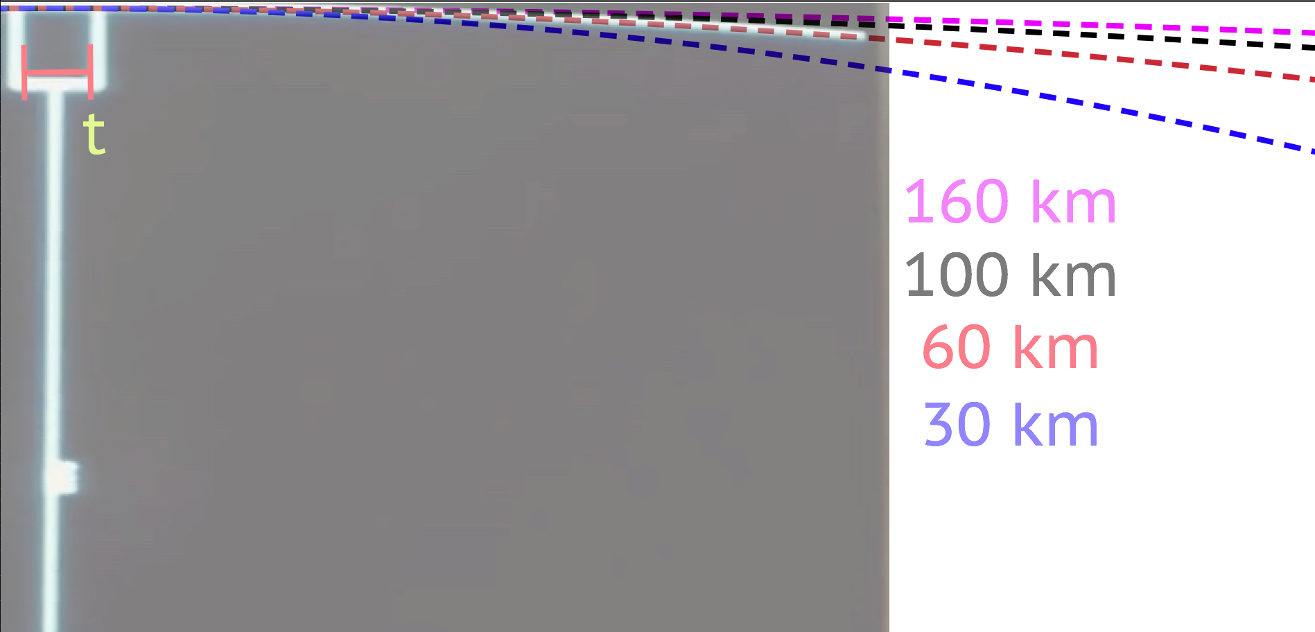
Figure 3a (to the right of the exhaust port chamber): As the plans zoom out further, the exhaust port chamber of width t = 186 m is shown with the curvature of DS1 (the square blob is the proton torpedo that has entered the port). The scale of t was determined based on information in Figure 2. Several circles with calibrated diameters based on the scales set in Figures 1 and 2 are shown. The 60 km diameter circle in red is arguably the best match to the curvature. Care was taken to match the point of contact of the circles to a common central location along the radial port.
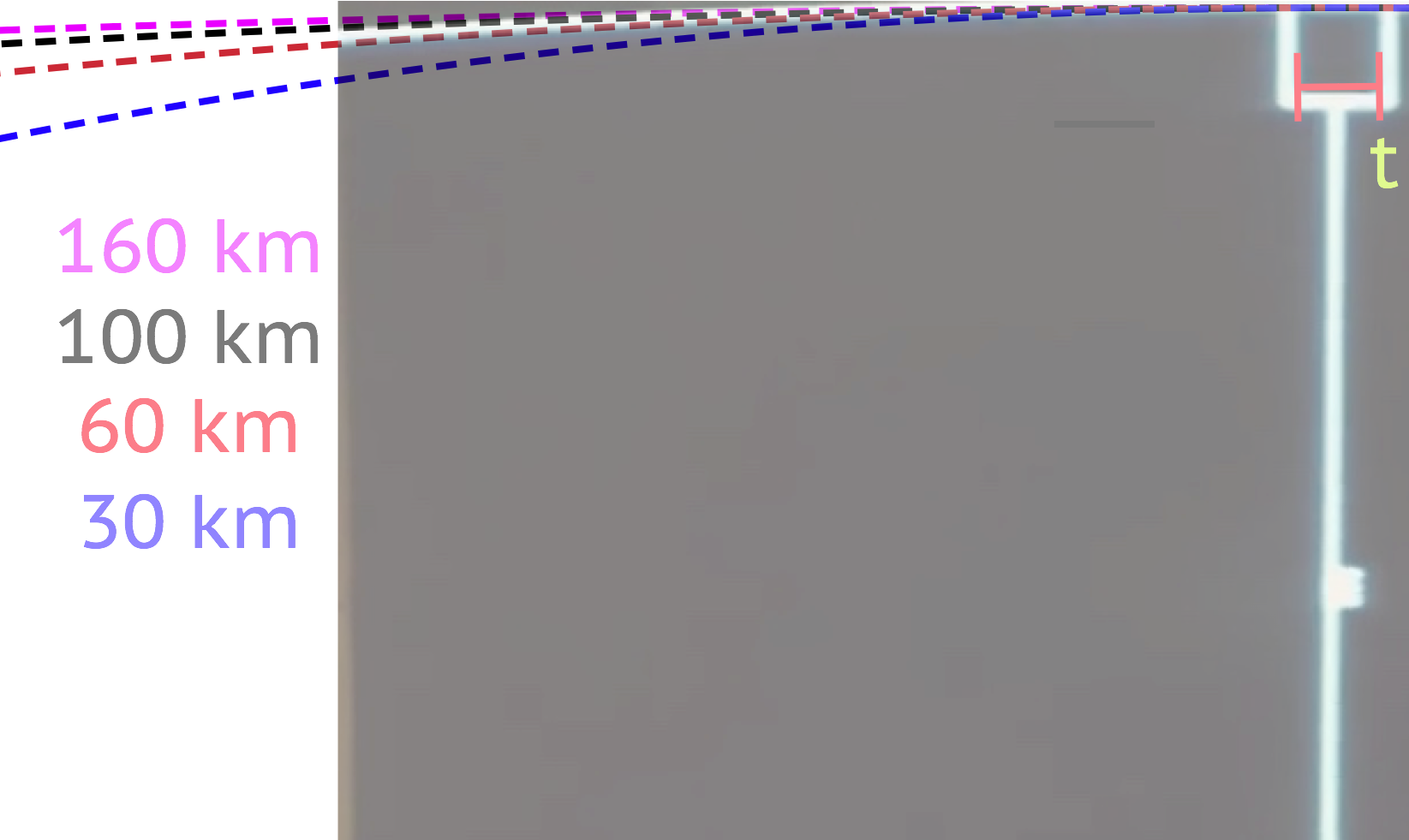
Figure 3b (to the left of the exhaust port chamber): The same idea as Figure 3a. The 60 km diameter is still arguably the best match, although is a little shy on this side. The 100 km diameter, the next best candidate, is shooting higher than the 60 km is shooting low. Since an exact mathematical fit wasn’t performed, the expected radius is probably a bit higher than 60 km, but significantly lower than 100 km.
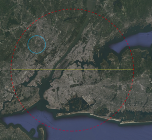
Figure 4: A 60 km diameter circle in red (with yellow diameter indicator) shown overlaid on a Google Earth image of the greater New York City region. The blue ring is an overlay of the scale of the Large Hadron Collider at CERN (about 8.5 km in diameter) — note the blue ring is not a scaled representation of the main weapon! The main message here is that a 60 km station, although smaller than the accepted 100-150 km, is still freakin’ HUGE. At this scale, there is only a rather modest indication of the massive urban infrastructure associated with New York City.
As another check on self-consistency, the diameter D is then used to calibrate the successive zooms on the station schematics, as shown in Figures 5 and 6. The length B = 10 km is the width of the zoom patch from Figure 5, X = 4.7 km is the length of the trench run, and b = 134 m is the width of one trench sector. From Figure 6, the width of the trench is estimated to be b’ = 60 m, able to accommodate roughly five x-wing fighters lined wingtip-to-wingtip. This indicates that the zoom factor is about 1000x in the briefing.
Figure 7 is a busy plot. It overlays several accurately scaled images over the 60 m trench, shown with two parallel red lines, to reinforce plausibility. Starting from the top: an airport runway with a 737 ready for takeoff (wingspan 34 m); a 100 m-wide yellow calibration line; a 60 m-wide yellow calibration line; the widths of an x-wing (green, Wx = 12.5 m, where I’ve assumed the wingspan is about the same as the length — there does not seem to be a consensus online; I’ve seen the value quoted to be 10.9 m, but it isn’t well-sourced) and tie fighter (red, 6.34 m); and a scaled image from footage of two x-wings flying in formation, with a yellow 60 m calibration line as well as a calibrated green arrow placed over the nearer one to indicate 12.5 m. As predicted, about five x-wings could fit across based on the still image. Also from this, the depth of the trench is estimated to also be 60 m. The scales are all quite reasonable and consistent. It is worth noting that if the station were 100 km, the next possible sensible fit to the arc length in Figure 3, the width of the trench would be about 100 m, twice the current scale. This would not be consistent with either the visuals from the battle footage or the airport runway scales.
In short, while there is certainly worthy critique of this work, I argue that, after a reasonably careful analysis of the stolen plans for DS1, all scales paint a self-consistent picture that the diameter of DS1 is very close to 60 km.
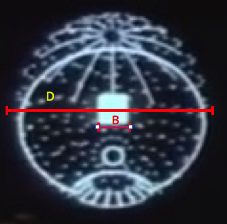
Figure 5: A zoom-out of DS1 in the briefing based on the stolen battle plans. D = 60 km is the diameter and B = 10 km is the width of the patch in the region of interest near the exhaust port.
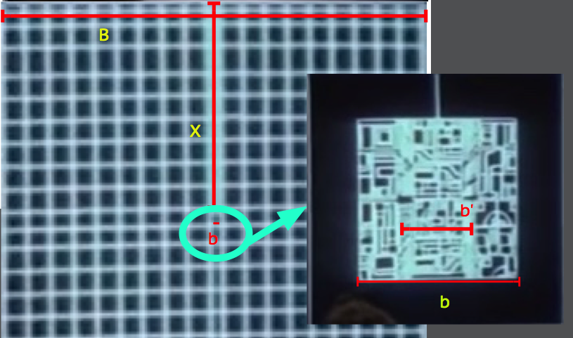
Figure 6: A zoom in in the region of interest patch near the exhaust port channel (see Figure 5) with B = 10 km. the channel itself is about X = 4.7 km long. The width of the channel is about b = 134 m. Inset is a further zoom of the insertion point along the channel. Width of the channel itself is about b’ = 60 m.
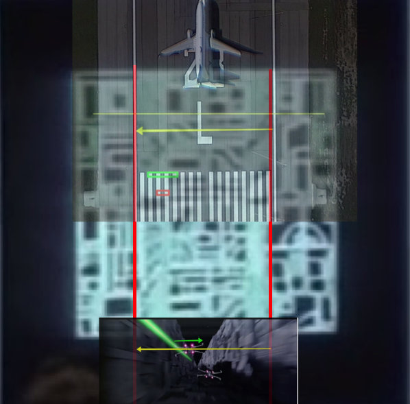
Figure 7: A zoom of the insertion point along the channel for the bombing run. Several elements are overplayed for a sense of scale and for consistency comparisons. The red parallel lines represent the left and right edges of the channel. From the top of the figure is a 737 with a wing span of 34 m. The 737 is on a runway (at SFO). Down from the 737 is a yellow line that represents 100 m. This would be the width of the channel if D = 100 km, which is clearly much too large based on the battle plans. The next horizontal yellow arrow is the 60 m width based on the scales assumed with D = 60 m. Next down, embedded in the vertical lines of the runway: a green block representing the width of an x-wing and a red block representing the width of a tie fighter. Finally, at the bottom is a shot from the battle footage. It has been scaled so the edges of the walls match the width of the channel (shown as a horizontal yellow arrow). The width of the near x-wing is shown with a green horizontal arrow, which matches the expected scale of an x-wing.